Translation of the article Automatizovaná linka na výrobu dielov oceľových konštrukcií originally published in magazine Strojarstvo.
The company MicroStep spol. s r.o. is engaged in development and production of CNC machines for cutting materials with energy-beam technologies i.e. plasma, oxygen, waterjet and laser. In addition to standard machines for cutting sheets, the company also supplies solutions for manufacture of specific types of parts.
Author: Ing. Alexander Varga, PhD., MicroStep, spol. s r.o.
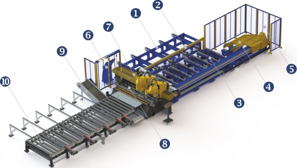
Fig. 1 – Line Visualization
1. Transverse input chain conveyor
2. Console with optical sensors
3. Input roller conveyor
4. Linear motion unit with hydraulic grippers for gripping and moving plates in the X axis
5. Security fence
6. MMI console
7. Static portal with technological equipment
8. Cutting table
9. Transverse output conveyor for unloading of finished parts
10. Output roller conveyor
To achieve high productivity machines tend to be equipped with systems for automatic feeding of sheets into the working area of the machine with the possibility of customer’s choice of the input tray capacity. Similarly, the output side is designed for automatic unloading of finished parts through an ejector and a conveyor. A machine designed this way is an automated work cell with minimum requirements for service personnel.
DS Machine Product Line
DS type machines have a static portal with the cut material moving in one direction (X axis) and the tool moving in the direction of the second coordinate axis (Y axis). Movement in the X axis is provided by a linear motion unit equipped with hydraulic grippers (point 4 in Fig. 1). Gripping of the material is fully automatic.
On the static portal supports are placed with installed technological equipment and their configuration is partially optional for customers. The standard set consists of a plasma cutting tool station for perpendicular or bevel cutting, an oxyfuel cutting tool station for cutting materials with greater thicknesses than the applied plasma source can cut and a drilling tool station with automatic tool exchange. The machines are supplied with plasma sources from Hypertherm or Kjellberg – according to customers’ requirements. To marking of the manufactured parts a marking system with a micro-punch unit is used, with an option to use other types of marking systems, for example an ink marker (inkjet).
The drilling tool station with spindle drive power of 26 kW allows drilling of hole of up to Ø50 mm diameter and is equipped with an automatic tool exchange system with a magazine for 6 tools. Tools with internal cooling are used. Fixation of plates in the drilling process is ensured by a pressure holder that also prevents chip from flying away. The pressure holder also detects the position of the drilled plate’s surface, allowing the drilling tool to approach the surface by fast feed. The drilling unit has programmable drilling cycles. The system is equipped with automatic measuring of the drill bit’s length.
 |
 |
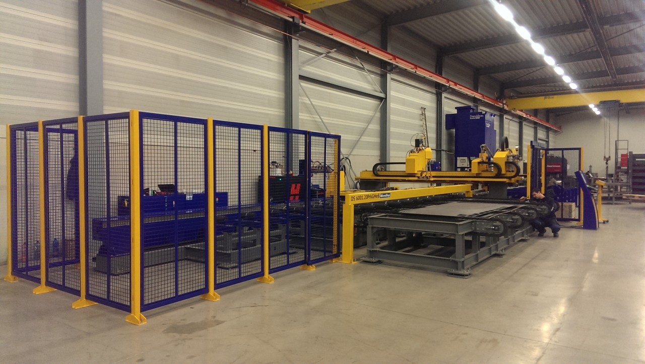
| Fig. 2 – View of the DS machine from the input side | Fig. 3 – View of the DS machine from the output side |
The work process of the machine is as follows: the material to be cut is deposited in the input tray that which is moved into the work area of the machine. After insertion and aligning, the material is gripped with hydraulic grippers and is pushed under the portal of the machine on the roller conveyor, where its width and length are measured by a laser sensor. The thickness is measured by a measuring system integrated into the gripper jaws. After measuring the dimensions of the input material, a cutting plan is automatically assigned to it and the production process starts .The production process begins with marking, continues with drilling and ends with cutting of parts and it is optimized to avoid unnecessary movement of material. The cut parts are tipped onto the conveyor belt by means of which they are then transported to a container for finished parts. The rest of the plate (waste) is pushed on the roller track and by mechanical sliders pushed to the removal position.
Complemented CAM Software
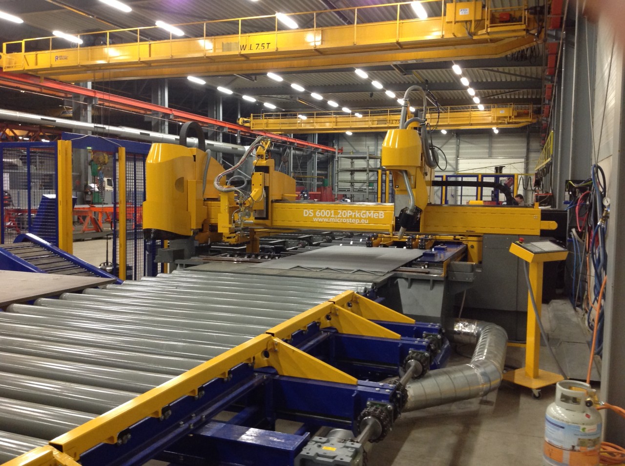
Fig. 4 – Portal of the machine with technological tool stations and the output conveyor with mechanical sliders